|
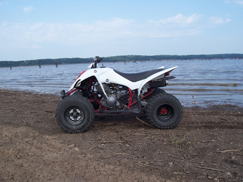
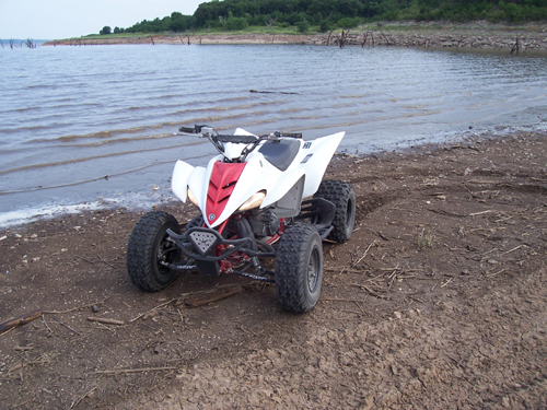
Project 2005 Raptor 350 |
|
|
|
|
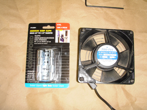
Ok, so I decided to take a shot at putting a cooling fan in my Raptor 350. Here are the components I started with. A Toyo 120mm 12 volt fan and some common wall mount broom clips. |
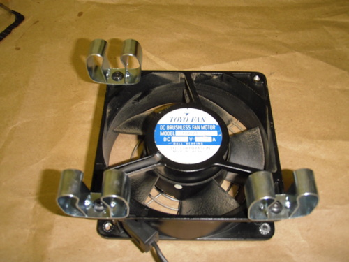
I tapped the holes and used button head screws to mount the clips. You can only use three as shown because the exhaust pipe is in the way. |
|
|
|
|
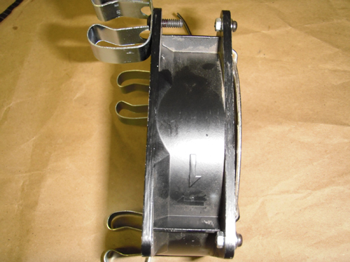
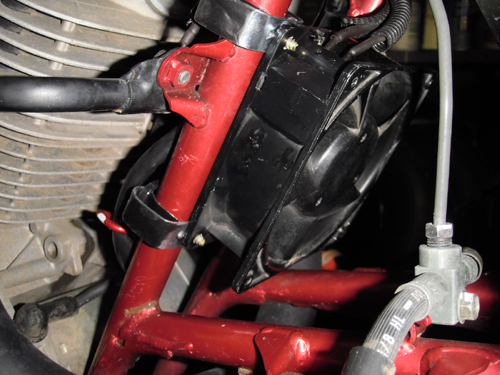
Make sure the arrow for direction of flow is pointing to the sides you mounted the clips on. I use the clips to make it quick and easy to take the fan off for certain situations. |
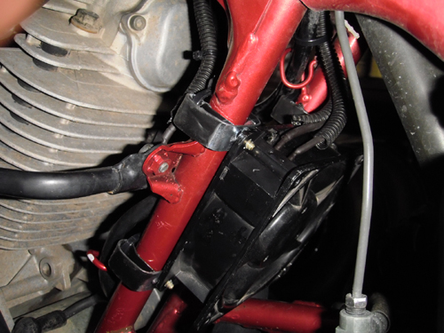
I bought the rubberized dip and tried to dip the clips in it to protect the frame. A few wraps of electrical tape is more practical. Anyway the fan clips on the frame as shown. |
|
|
|
|
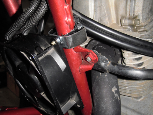
I soldered and heat shrunk the wires to the fan connectors. The negative side I attached to the fender brace mounting bolt. It is not pictured but I used bullet connectors to make it easy to remove. |
This view shows why you can't put the fourth clip on. The exhaust pipe is just too close. |
|
|
|
|
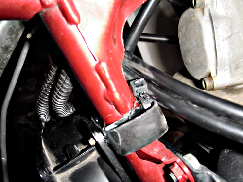
For added insurance I ran a zip tie through the back loops of the clip to make sure the fan wouldn't accidentally pop off for any reason. Amazingly it fits pretty tight. |
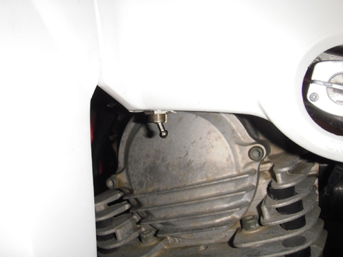
For the on/off switch I drilled a hole in the lower lip of the gas tank cover and mounted the switch pointing down. I ran the wire along the frame with the existing wiring. At the battery I used a fuse holder and a 10 amp fuse. |
|
|
|
|
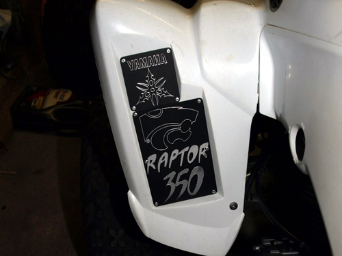
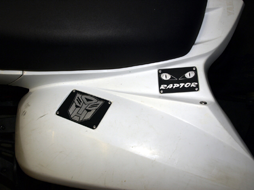
Custom labels I made on the CNC mill at work. |
|
|
|
|
|
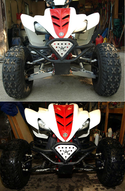
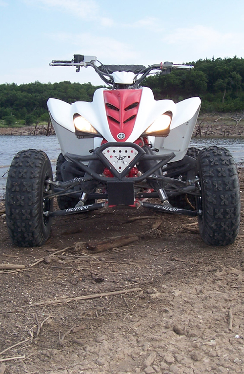
A-Arm swap. Added Full Flight +2 arms for 4" total in the front. Also lowered it 1 1/4". |
|
|
|
|
|